

David's
<Tech Repair\>
Your friendly neighborhood IT Guy
davidstechsupport
Ethernet House Routing
Sections:
-
Project overview
-
Ethernet Explained
-
The tools used
-
Project explained
-
Closing comments
Project overview
This is a project that I had planned since getting OmniFiber internet; it's no surprise that I'm a huge tech enthusiast and enjoy having my devices connected to the internet. The first part of this project involved taking measurements to determine the distance the cables would need to cover, as well as researching all the necessary components to not only have enough cable but also to create my own.
Why hardwire my house? This is a question that I get asked when I bring up this project because anyone who uses Ethernet for home internet usually has the devices in the same room as the router and only needs a few feet for a cable or does what I would do at my dad's house and run a long Ethernet cable either through the house or around the outside. Hardwiring cables through the walls not only makes it more efficient for connectivity but also adds a sort of "professional" style (in my opinion) to the house.
Some pros and cons come with internal cable routing (not just for ethernet):
Pros:
-
Increased reliability and consistency for the internet connection
-
Higher speeds (depending on house size)
-
Better security (if you would disable WiFi and only use wired)
-
Future-proofing—especially if you are going with CAT 8 cables, this is the latest CAT cable and will last for years to come. This would only need to be replaced when internet speeds catch up to it or the cable gets damaged.
Cons:
-
Installation and cost—this depends on the scale of your project and the supplies required to complete it. The cost also varies depending on whether or not you hire someone to do the project.
-
Cable mess—This is only a con if, when routing the cables, the person doing it doesn't properly organize them during the process. Basically, whoever routes the cable (let's say through the attic) just tosses the cable on the floor and calls it a day.
-
Additional cables—depending on how many devices are going to be connected, this could potentially raise the cost and extend the project time frame
-
Feel free to skip this section if you are not interested in the history of Ethernet, or continue reading if you would like to know more about the origins and history of the internet cable.
Ethernet has been around since 1973, when Robert Metcalfe and David Boggs invented it at the Xerox Palo Alto Research Center in California.
There are currently seven categories of Ethernet:
Category 5 (Cat 5): Supports speeds up to 100 Mbps and bandwidth of 100 MHz. It is suitable for standard Ethernet and Fast Ethernet applications.
Category 5e (Cat 5e): An enhanced version of Cat 5, it supports speeds up to 1 Gbps (Gigabit Ethernet) and a bandwidth of 100 MHz. It reduces crosstalk and improves performance.
Category 6 (Cat 6): This is currently the most common category used in households and office buildings. Cat 6 supports speeds up to 10 Gbps for distances up to 55 meters and a bandwidth of 250 MHz. It is designed for Gigabit Ethernet and is suitable for high-speed networks.
Category 6a (Cat 6a): An augmented version of Cat 6, it supports speeds up to 10 Gbps for distances up to 100 meters and a bandwidth of 500 MHz. It provides better shielding to reduce interference.
Category 7 (Cat 7): Supports speeds up to 10 Gbps and bandwidth of 600 MHz. It uses shielded twisted pairs (STP) to minimize crosstalk and improve performance in high-interference environments.
Category 7a (Cat 7a): An advanced version of Cat 7, it supports speeds up to 10 Gbps and a bandwidth of 1000 MHz. It is designed for future-proofing high-speed networks.
Category 8 (Cat 8): The latest standard, it supports speeds up to 25 Gbps or 40 Gbps for distances up to 30 meters and a bandwidth of 2000 MHz. It is primarily used in data centers and high-performance computing environments.

Some major dates of Ethernet:
-
1973: Ethernet was invented by Robert Metcalfe and his team at Xerox PARC, aiming to facilitate communication between computers using coaxial cables.
-
1980: The technology was commercially introduced, marking its entry into the market.
-
1983: Ethernet was standardized as IEEE 802.3, establishing a formal framework for its implementation.
-
1998: Celebrated its 25th anniversary, showcasing its adaptability and evolution alongside advancements in computer technology.
-
Ongoing Developments: Ethernet continues to evolve, supporting higher bit rates and more complex networking requirements, solidifying its role as a cornerstone of local area networks.
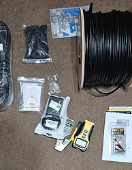
What I used
Before I get into the project, lets go over what I used
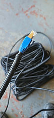
This is the cable used for the job; I decided on category 8 instead of 6 or 7 due to the speeds that are supported and cat 8 being the latest version. Although Cat 8 Ethernet is considered overkill for residential buildings, I will not need to worry about upgrading it for a long time if I ever need to. This also had 10 RJ45 connectors included, which is a nice bonus.
Note: I am going to use the remaining cable in this spool for custom cables that I will sell on the Facebook Marketplace. Once this spool is empty, I will begin making custom cables using Category 6 cable.


The tools needed to make this project work—I was able to strip, crimp, and test the cables using only two tools. I don't have very many tools for tech work outside of hand tools, so I decided to start my collection with Klein Tools, and the brand does not disappoint. The bonus connectors are also great for future cables.
The splitter was needed for this project. I have a few devices in my living room that have an Ethernet port (Xbox, DVD player, and TV), and I wanted them all to be hardwired instead of wireless to keep consistent speeds. The splitter saved me time by removing the need to route multiple long cables through the attic. I may route those later on and use a multi-port wall plate.

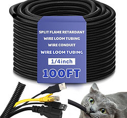
I needed to add the cable sleeve to the project since the primary cable routed through the wall will also be routed through the attic. This sleeve protects against chewing and heat while being easy to trim to get the right length without the hassle.
Good for the project, but I plan on getting pass-through connectors in the future for easier cable making. I will admit, I meant to get pass-throughs, but I didn't realize I purchased the wrong ones until I started working on this project; I was still able to make do with what I had.


The boots, in my opinion, are more for looks rather than functionality since their only use is to prevent the connector clip from snapping. Similar to the pack of connectors, I used a few for the project and the rest for custom cables.
Since I did not want to spend the extra money to get wall plates with built-in coax and ethernet ports, I grabbed a pack of these couplers that I will fit into the ethernet wall plates to allow access to both connections.


The wall plates add a more professional look when the project is finished, giving an official connection point instead of a hole in the wall. Unfortunately, I could not find any Category 8 wall plates, but these will do just fine for now.
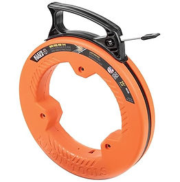
The fish tape is just what I needed to get the cable pulled up and down the wall to connect it to the wall plates. To use this, all I needed to do was wire-tape the end of the cable to the end of the fish tape and reel it in from point A to point B.
Other tools that I used are
I linked each of these if you're interested in getting them for yourself. since I used them more than once, I'm not going to add them in the process of the project
The Project Explained
Here are the important steps from start to finish for this project:
-
Measure distance
-
Make a test cable (make sure I do it right)
-
set wall plate spots
-
Make one end of the in-wall cable
-
Route the cable through the wall/attic
-
Make the other end of the cable
-
Test cable
-
Conceal in-wall and set wall plates
-
Set up an Ethernet splitter
-
Make cables for other devices
-
Internet speeds on connected devices
Alright, now that the interesting facts and tools are out of the way, let's get into the project itself. This project from start to finish only took about 4:30 hours to complete over the course of a few days.
- 1:20 hours to measure distance and make the primary cable and apply protection sleeve
-2 hours to route cable through attic from office to living room (drilling and measurements)
-1 hour to make the 4 device cables (couple errors)
-10 minutes to connect everything and run speed tests
Cable Protection Sleeve
Measuring the distance was the easiest thing about this; all I did was run my rope tape measure from my office wall to my living room wall to get the base distance, then measure the height of the wall and add a few feet to ensure I would get the right amount of cable cut with some to spare for no stress. After I finished the measurements, I made a short test cable to understand how to make an Ethernet cable and test it properly. Before I started drilling holes in the wall and climbing around the attic, I decided where the wall plates would be put. Luckily, the existing coax wall plates were perfect.
The reason why it took so long to apply the protection sleeve was due to it being extremely "tough," I guess is the word to use; it didn't want to open easily, and every few feet it would bend the wrong way, causing me to go back and fix it.
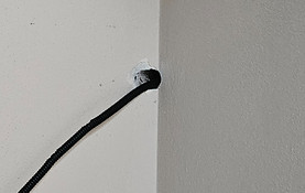
The garage routing was easy since there was a coax cable already there and routed, but there was a downside when it came to the office route: I couldn't get the cable through the wall and up to the attic for my office coax port, so instead, I made a hole in the ceiling for the route point.
Office Route
Garage to attic
Attic to office


Now, when it comes to making an Ethernet cable, it's actually a pretty simple process. The steps are easy to follow:
Measure and Cut the Cable
Decide the length of cable you need.
Use cable cutters to cut the cable cleanly to the desired length.
Strip the Outer Jacket
Use a cable stripper to remove about 1.5 inches (3.8 cm) of the outer jacket from both ends of the cable.
Be careful not to nick or damage the inner twisted pairs.
Untwist and Arrange the Pairs
Untwist each pair of wires carefully.
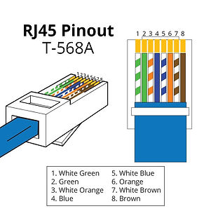
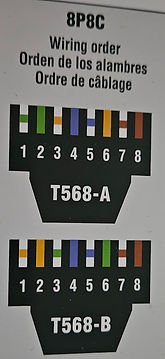
Arrange the wires according to the wiring standard you want to use (T568A or T568B). I used T568B:
Pin 1: White/Orange
Pin 2: Orange
Pin 3: White/Green
Pin 4: Blue
Pin 5: White/Blue
Pin 6: Green
Pin 7: White/Brown
Pin 8: Brown
Trim the Wires (if you're not using a pass-through connector)
Hold the wires flat and trim them evenly to about 0.5 inch (1.3 cm) from the jacket.
Insert Wires into the Connector
Carefully insert the wires into the Category 8 RJ45 connector, ensuring each wire goes into the correct channel.
Push the cable jacket inside the connector to provide strain relief.
Crimp the Connector
Place the connector into a Category 8-compatible crimping tool.
Squeeze the crimping tool firmly to secure the connector onto the cable.
Repeat for the Other End
Repeat steps 2 through 6 for the other end of the cable.
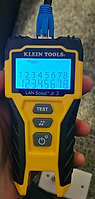
Test the Cable
Connect both ends of the cable into a tester and ensure point 1 to 8 are showing passed
Since making the primary cable was easy, I made four more for the project. As I mentioned before, I didn't use pass-through connectors for this. I went through about 13 connectors to make these since the wires didn't line up correctly when crimping on two of the cables, requiring me to cut them shorter and use another connector.


Before testing the internet speeds and hitting complete on this project, all that left to do is set up the Ethernet splitter and connect the devices.
The only downside to this splitter is that it only supports up to 1 Gbps, but seeing the final speeds (next part of this section), this works just fine.
This part was incredibly easy since it was literally just plug and go with the additional mounting of the splitter itself. The only difficulty was connecting the TV since I have it mounted so close to the wall; it took a minute to find the port on the back.
Velcro Backing

All Connected

Now that all the cables have been made, all the wiring is finished, and everything is connected, all that is left is the final touch, the speed tests.
I connected three devices with this project: my TV, Blu-ray player, and Xbox Series S. Unfortunately, I didn't get that great of speed increases, but I got a small boost. The Blu-ray player didn't have a speed display in its settings, so I don't have an image for that.
Roku TV

I forgot to take a pre-wired picture but it was around 75Mbps before the wiring
Xbox Before

Xbox After

Although it's not the best improvement in speed, it's still nearly 100 Mbps more than what I had. I'll look into this later on to see if theres anything i can do.
Closing Comments
This project surprisingly took only about three hours to complete, with the most time-consuming task being the creation of the Ethernet cables. Overall, it was an enjoyable experience that combined a long-standing interest of mine with valuable learning opportunities. Having never worked with cables beyond plugging them in and organizing them, I was uncertain about the challenges of splicing and crimping, but I was determined to figure it out.
The most challenging aspect turned out to be making the connectors. It took several attempts, but I eventually succeeded in aligning each pin perfectly. Since I used Category 8 cables, I had to strip away not one, not two, but three layers from the internal wires before arranging the eight individual wires for the Ethernet connection. The first connector took me about 30 minutes to complete and crimp onto the test cable. Once I finished and tested the test cable—successfully on the first try—it took only 5 to 10 minutes to create the connectors for the in-wall cables and even less time for the individual device cables.
Since I have completed this project and created over four custom-length cables, I have thought about selling custom cables on my Facebook Tech Support Page.